 |
| VNA Options Dialog |
cialog with the N2PK VNA
cialog started off as an interface program for the CIA-HF. While part of the program is devoted to uploading data from the CIA-HF, the remainder of the program is devoted to graphing data, and comparing data saved in files from previous sessions. After I built my N2PK VNA, it made sense to modify cialog to upload data from the VNA, and graph it using the same program code used to graph CIA-HF data. While this does the VNA a disservice, since it has much greater range and resolution compared to the CIA-HF, it is a simple extension to the program, and for most antenna work, the results are very useful.
Both the CIA-HF and the VNA should be viewed as peer sources of captured impedance data which is uploaded to cialog. Once in the program, all data is stored in the same format, and the source of the data no longer matters. Data graphing, file operations, and translation through a feed system can be equally applied to the data without concern for the source. Data can be compared between the CIA-HF and the VNA, if desired.
The cialog capture mode, either CIA-HF, or VNA, is selected with commands on the File menu. File->Use the CIA-HF sets the CIA-HF mode, and File->Use the VNA selects VNA capture. When cialog is capturing data from the VNA, the window title, main menu, and statusbar are changed to indicate that the VNA is in use. The capture source is saved when the program exits, and reused when the program starts.
The N2PK VNA is described on the N2PK web site. Additional information is located on my web site.
VNA data is stored and manipulated by cialog with the same representation used by the CIA-HF. Data measured in Ohms (resistance, reactance, impedance) is rounded to 0.1 Ohm resolution. SWR is rounded to 0.01 unit resolution. The inherent VNA resolution is greater than the CIA-HF, but the single representation was adopted so that the same program code could be used with either capture device. Other VNA software may indeed report results with greater resolution.
Data measured in Ohms is also limited to a range of plus and minus 999.9 Ohms. SWR data is limited to a maximum value of 99.99. These range limits come from the CIA-HF.
The final limitation taken from the CIA-HF involves the data capture intervals, or frequency spacing between sample points. The predefined widths, adopted from the CIA-HF, are 1, 2, 5, 10, 20, 50, and 100 KHz.
cialog measures the complex reflection coefficient, which is converted to resistance, reactance, and SWR. Impedance is the computed as the square root of the sum of the squares of resistance and reactance.
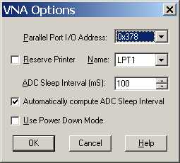
The VNA connects to the computer via a parallel or printer port. The particular parallel port address is specified on the VNA Options Dialog. When capturing data from the VNA, cialog must have access to the parallel port hardware. On recent versions of Windows, this access is normally denied. In those cases, an auxiliary program can be used to change the permissions of the cialog program. One program that we have found works well is UserPort 1.0.
The options that pertain to the VNA are set on the VNA Options DIalog. The VNA Options Dialog is displayed with the VNA->Options menu command. You must be in VNA capture mode in order for this submenu to be available.
|
|
| VNA Options Dialog |
The following controls are defined:
cialog reads and uses VNA.CFG files, which were defined by and used with the VNA software written by N2PK. The file is a set of name/value pairs that specify a number of different parameters. Please consult the N2PK VNA software, which includes VNA.CFG examples. Here is one of those examples, which shows the general structure and syntax of the file.
| Port=0x378 | (Hex, set this to the address of the parallel port used by the VNA) |
| Clk=148.344 | (MHz, set to the actual master oscillator frequency for the VNA) |
| ADCdel=10 | (ms, delay between frequency program and first ADC read (ckt/ADC settling time). Use '10' as a default.) |
| cfp=1 | (set to '1' for Continuous Frequency Programming, '0' otherwise, Use '1' as a default) |
| Z0=50 | (ohms, basis for reflection coefficients and center of Smith Chart. Normally 50 Ohms) |
| Cop=0.039 | (0.039 pF for open flat ground female SMA chassis connector, excess shunt (fringing) capacitance of the Open cal standard beyond the reference plane. Use 0 if you don't know a better value.) |
| Rsh=0 | (0 ohms for a short cal std on a flat ground female SMA chassis connector, series resistance of Short cal standard. Use 0 if you don't know a better value.) |
| Lsh=0.0 | (0.00 nH for the SMA short cal std, series inductance of the Short cal standard. Use 0 if you don't know a better value.) |
| Rld=50.000 | (Series resistance of the Load cal standard, usually about 50 ohms. Use an accurately measured value or the nominal value.) |
| Lld=0.15 | (0.15 nH for 4x200 ohm 0805 on flat ground female SMA chassis connector, series inductance of the Load cal standard. Use 0 if you don't know a better value.) |
| Cld=0.23 | (0.23 pF for the female SMA load std, excess shunt capacitance of the Load cal standard beyond the reference plane. Use 0 if you don't know a better value.) |
|
Raw=0 |
(set to '1' to append raw data to *.RAW files, '0' if not) |
|
VNA.CFG Example |
|
The parameters have default values which are indicated in the following table.
| VNA.CFG Parameters and the Default Values | ||
| Name | cialog Default Value | Description |
| Port | 0x378 | Parallel Port address (hex notation) (ignored by cialog, use the Options Dialog) |
| Clk | 148.344 | Master Oscillator frequency (MHz) |
| ADCdel | 10 | Delay between setting DDS chips and starting the ADC (integer milliseconds) |
| cfp | 1 | Continuous Frequency Programming (integer) |
| Z0 | 50.0 | Basis for Reflection Coefficient calculations |
| Cop | 0.0 | Open Standard shunt capacitance (pf) |
| Rsh | 0.0 | Short Standard resistance (Ohms) |
| Lsh | 0.0 | Short Standard inductance (nanohenries (nH)) |
| Rld | 50.0 | Load Standard resistance (Ohms) |
| Lld | 0.0 | Load Standard inductance (nanohenries (nH)) |
| Cld | 0.0 | Load Standard shunt capacitance (pf) |
| Raw | 0 | (integer, unused by cialog) |
One of the file parameters is the VNA I/O port address. This value is always ignored by cialog, using instead the port address on the Options Dialog.
cialog looks in two folders for VNA.CFG files. The first folder is the folder that holds the cialog executable program. The second folder is the data folder used to hold cialog data files. These files are read whenever cialog opens the VNA device. The VNA is opened whenever cialog enters the VNA mode, including when the program begins. The VNA is also opened whenever an option is changed on the options dialog, and the options are saved.
It is not necessary to use the VNA.CFG files. If neither file exists, then a set of reasonable default values, described in the previous table will be used. It is not an error if a parameter name is not defined. It is not an error if a parameter name is defined more than once. In this case, the most recent value set will be used. Unrecognized name/value pairs are ignored. Parameter names are case insensitive. Comments are enclosed in parenthesis.
If you wish to use any of the calibration standard residual parameters (Cop, Rsh, etc) in cialog, then you must us a VNA.CFG file. There is no other way to specify them. If they are specified, however, they will be used in calculations.
VNA data capture is started with a menu command. There are two choices. One choice reuses OSL calibration information, the other does not.
The VNA->New Capture menu command displays a dialog box which is used to specify the starting and stopping frequencies of the capture range. The sample width is also specified. When the OK button is clicked, cialog will use a simple message box to prompt for the connection of the open, short, load, (OSL) and device under test (DUT) devices. You should connect the appropriate device at the corresponding prompt, then click OK. After all of the calibration standard and DUT is captured, the resulting data will be graphed.
In many cases, the same range parameters are used over and over again, as changes as made to the DUT. So long as the range parameters do not change, the calibration standard information can be reused (assuming that they have been captured once). To use this feature, select the VNA->Redo Last Capture menu command. In this case, there will be a single prompt, for the DUT. The OSL information will be reused.
While this can be a great time saver, be sure that changes in conditions have not invalidated the calibration standard data. The worst case is to remove power from the VNA. Drift over time and temperature may also reduce the value of the calibration data. The most accurate results will be obtained when calibration is done as part of every capture.
If your VNA uses the LTC2440 analog to digital converter chip (part of a fast detector), and the control line is connected to the computer interface, then you can change the ADC conversion rate. This is accomplished through a command on a submenu located on the VNA menu.
In order for rate changing to work, the ADC SDI (Serial Data In) signal (pin 7) must be connected to the RF DDS Serial Load pin. This is most easily accomplished by connecting to pin 19 of the bus interface chip. See this page for more details. cialog does not support control signal mapping; there is but one correct way to connect and control the ADC.
As the conversion rate increases, the quality of the data decreases. Please consult the Linear Technology data sheet for more information on the 2440 ADC. Given the compromised data representation used for the VNA in cialog, the differences due to conversion rate will probably make little difference. So, go fast.
The time necessary to make a measurement is not controlled exclusively by the ADC conversion rate. There is a setup time delay, which is nominally 10 ms. This is the delay between changing the DDS outputs and starting the ADC conversion. In cialog, this rate can be controlled by changing the VNA.CFG file.
This setup delay effectively establishes the upper conversion performance of the program. 10 ms implies 100 setup periods, or 100 samples. Two samples are required to make a single measurement, so the maximum data measurement rate is approximately 50 frequency points per second. This assumes an infinitely fast ADC.
After the setup time period, the ADC conversion is started. A second delay then occurs, waiting for the ADC to complete. This delay is a direct function of the ADC conversion rate. The slowest, but most accurate, conversion rate is approximately 7 conversions per second. The waiting period is approximately 140 ms. The fastest, and least accurate conversion rate is 3520 conversions per second, which is equal to a 0.28 ms waiting period. It is desirable to spend as much of that period as possible in a programmed sleep, as opposed to passing time in a busy-wait loop. You can either specify the sleep time, or, allow cialog to compute it as a function of the conversion rate. These choices are made on the Options Dialog. If you specify a sleep time which is greater than the conversion delay, then the overall measurement rate will simply slow down.
cialog does not support data averaging.
The following example shows the impact of changing the conversion rate on the data collection time. A test capture of approximately 191 points, at 7 conversion per second, had a data collection time of 60 seconds, as measured on a clock. The setup delay was 10 ms. The ADC rate was then increased through the available rates, up to 880 conversion per second. The following table relates conversion rate to data collection time.
| Conversion Rate to Data Collection Time Example | ||
| ADC Rate | Time (seconds) | Actual Rate |
| 7 CPS | 60 | 6.3 |
| 14 CPS | 32 | 11.9 |
| 28 CPS | 18 | 21.2 |
| 55 CPS | 12 | 31.8 |
| 110 CPS | 8 | 47.7 |
| 220 CPS | 6 | 63.3 |
| 440 CPS | 6 | 63.3 |
| 880 CPS | 5 | 76.4 |
The actual rate was computed by dividing the total number of ADC readings (382) by the elapsed time. The actual rate increases, but is ultimately limited by the setup delay.
Saving VNA data is no different than saving CIA-HF data. Once data is captured from the VNA, and visible on the graph, the source of the data no longer matters. All file operations defined for the CIA-HF apply to the VNA.
With the CIA-HF, the only way to make remote measurements is to specify a feed system in cialog, so that the measured impedance data can be transformed back to the load side of a transmission line. The VNA allows this mode of operation, but also provides a second mode. The OSL calibration can be done on the load side of a transmission line. Each mode has advantages and disadvantages.
Performing OSL calibration at the end of a transmission line should provide very good accuracy. It does require, however, access to the far end of the line. If the line is on top of a tower, this might be difficult. If a feed system is used, it may be necessary to experimentally tweak the length of the line to compensate for variations in the particular cable. In any case, it probably makes no sense to specify a feed system and perform remote OSL calibration.
Using a feed system with the VNA is no different than using one with the CIA-HF. Specify a feed system, then select it with the Feed System->Select Feed System menu command. All measured impedance data will then be transformed to the load end of the transmission line.
The portion of cialog that supports the VNA is based upon the VNAccess and VNAgra programming libraries. These libraries are contained within the files vnacess.dll and vnagra.dll. These files are normally installed in the same folder that contains the cialog executable. If either file is missing, cialog will not be able to capture data from the VNA. Neither dll (dynamic link library) file is needed for interaction with the CIA-HF.
These library files are installed as part of cialog, at and above version 1.08.
Last update:
Sunday, October 31, 2004 11:38:12 AM
Back to the cialog Home Page