 |
 |
| The First Payload Implementation | Camera Payload on the Scrambler 2 |
Greg Ordy
The phrase solid-state in the title of this page might create the impression that I am talking about a solid-state image sensor, as opposed to an old-fashioned vidicon tube. That's not what solid-state means - in this context. By solid-state I mean that the video data is stored in solid-state (semiconductor) memory, as opposed to a traditional video tape, or even a small disk drive.
Flying a moving picture camera in a model rocket has been a goal and challenge that is as old as the hobby itself. In the early years, the only choice was to fly a camera with photographic film, such as an 8 mm or Super 8 mm camera. Estes Industries once sold a camera named the Cineroc, that was based on photographic film. Even if you really cut back on the camera weight (back then, most cameras were made of metal, not plastic), it was still at the upper end of the weight and size limits of model rockets, especially at that point in the hobby.
As the years passed, cameras became lighter, and rockets became larger. At some point, the video camera joined the photographic camera as a viable technology for putting a moving picture camera in a model rocket. Now it was possible to directly transmit the video signal from the rocket down to a receiver on the ground. Not only did this remove the need to have a recording mechanism on the rocket, but it was no longer necessary to wait for film to be developed. Gratification was nearly instant. On the other hand, video images often do not have the quality of traditional film-based photography.
There were still issues. Transmitting a video signal across several thousand feet is not trivial. Some solutions required an Amateur Radio license, so that certain frequencies and power levels could be used. Signals were transmitted on some part of the UHF band. In order to receive the signal with minimum noise, it was necessary to use a directional receiving antenna. This meant that a human had to track the ascent and total flight of the rocket while pointing an antenna directly at the rocket. That is not easy. Even if you were able to track the rocket, the transmitting antenna would tend to roll and tumble, and this would change the signal level received on the ground, adding instability to the picture.
While it might be possible to fly a video camera with an integrated recorder (camcorder), the spinning video head would tend to act like a gyroscope, and possibly cause the rocket to fly in an unexpected manner. Even if that is not a problem, video transports are usually not designed to stand the G-forces present in a model rocket flight.
And even if you solved all of the technical problems, you still had a large and complex rocket, and an investment of at least several hundred dollars.
In recent years, video cameras and associated technology have continued to drop in size and cost. When we started to build and launch rockets again, we decided it was time to evaluate the existing technology and see if there was a camera solution that would work well, and also not break the bank with its cost. This page describes our approach and solution. The heart of the system is the Aiptek Mega Cam. This camera takes both still and video pictures. The video data is stored in a 16 megabyte memory in the camera. The camera is quite small, measuring 1" X 1" X 3.5". The camera is very lightweight, and in May of 2002, costs approximately $90 (USD). Because of the small size and weight of the camera, the rocket can fly on the recently-introduced Fat C engine. In other words, a large and expensive rocket is not needed to fly this video camera. We usually use D engines. The whole system costs less than $100 (USD). No doubt the price will only drop as time passes.
NOTE: Aiptek appears to be changing the name of the camera. At the time that I bought my camera, it was called the Mega Cam 1.3. My physical camera is labeled with the name MegaCam. Recent visits to the Aiptek web site show that the camera is now called the Mini PenCam 1.3. The camera we used has 16 MBytes of flash memory, and 16 MBytes of SDRAM. Sadly, there is another camera called the Mega PenCam 1.3. This unit has less memory capacity. The SDRAM capacity directly limits the video duration.
Please see my main Rockets page for even more links.
Aiptek Mini PenCam 1.3: The Aiptek web site.
USB Only: Where I bought my camera. Now apparently called Memory Only.
Modifying a PenCam for External Control: A good description of how to modify another Aiptek camera for electronic shutter control. As best as I can tell this camera would following nearly the identical procedure.
AYUCR Camera Controller: Lots of information of taking still pictures from rockets.
Kite flyers have developed some very sophisticated camera platforms. Search for KAP (kite aerial photography) on any quality search engine.
There are many small digital cameras on the market these days. Most all are primarily designed to be still cameras, and they perform movie/video capture as a secondary function. There are several issues to consider before selecting a camera.
| Camera Selection Issues | |
| Issue | Comment |
| Resolution | The number of pixels in the image sensor. Many small and light weight cameras have 640 X 480 resolutions in still mode. This is not too bad, but be careful that the resolution does not drop when capturing video. Quite often, the video resolution is 320 X 240, which appears to be near a video conferencing standard. This resolution is just too poor for rocket videos. The camera we used has a still resolution of 1248 X 640, and a high quality video resolution of 624 X 480. At this time, this was the only camera I could find with such a high video resolution. |
| Lens | Most of the cameras that are suitable for a small rocket will have a fixed focus lens. Apparently the typical optimal focus distance is near 6 feet - the distance for snapshots of people. A true zoon lens might not be desirable, since the rocket motion would be accentuated. A wide-angle lens might be interesting. |
| Memory | By memory, I mean how many seconds of video can be saved. If the video is going to on-board memory, you can be sure that there will be a limit. This camera specifies a time limit of 30 seconds in high quality video mode. We often obtain longer times - up to 90 seconds. I suspect that this has to do with image complexity, and the ability of the software compression to do its job. Note that very long flights might be cut off before the flight ends. Another alternate is to switch to the lower video quality mode, where the time minimum is 120 seconds. That should be more than enough for just about any flight. |
| Frame Rate | Frame rate is measured in frames per seconds. Do not expect the normal video value of 30 frames per second. The frame rate of this camera is 10 frames per second. While that might sound poor, it was the best of all of the competition at the time of purchase. Of course while a higher frame rate is desirable, that will consume more memory per second, reducing the overall capture time.. |
| Size | Smaller tends to be better in this application. |
| Cost | Even if you are willing to spend a lot of money, there are not many choices. At less than $100, I considered this to be a reasonable cost. |
| Audio | Recording audio would be nice, although the memory consumption would rise. This camera does not record audio. If I really wanted to add audio, I would add a separate solid-state miniature audio recorder, and synchronize the picture to the sound with non-linear editing software on a computer. |
I suspect that over time the similar cameras will continue to drop in price, increase in capabilities and capacity, and decrease in size. This will only make it easier to get a camera up into the air.
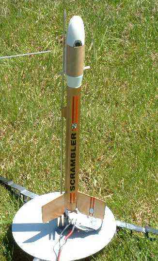
Finally, the camera arrived. How were we going to launch it? Heading down to the basement, the line-up of rockets included an old Estes Egg Scrambler 2. This is a D-powered rocket designed to launch an egg. The payload section had a stepped up diameter of 1.6 inches. The camera just fit within that diameter. It seemed like we had our rocket. Further hunting through the parts box revealed adapters, body tubes, and a nose cone (a Big Bertha nose cone) of the desired size.
The camera is operated with two buttons. The first button is the power/mode button. Pressed once, the camera turns one. The camera automatically turns off after a minute of inactivity. Each additional push of the power/mode buttons cycles to another mode. Modes include still pictures, videos, erasing pictures, and several other typical digital camera functions.
Once the mode is set, the second button executes the action. The action, for example, could be snapping a still picture, starting/stopping a video, or erasing a picture.
In order to be able to press these buttons, we drilled two 1/4" holes in the plastic nose cone. We used a pointed object (envelope opener) to press the buttons through the holes in the nose cone. The camera emits beeps with each button press, so it's easy to make sure that the camera is operating in the correct mode (even when it is buried within a rocket payload section).
The following two pictures show the elements of the payload section, and the complete rocket on the launch pad.
|
|
|
| The First Payload Implementation | Camera Payload on the Scrambler 2 |
We cut an opening in the nose cone that exposed the camera lens. The payload body tube came right up to the level of the bottom of the lens. The dowel that pinned the body tube to the adapter was also used to secure a rubber band that ran across the top of the nose cone. This rubber band held the nose cone onto the body tube. We cut a slot on the top of the nose cone so that the rubber band would not slip off.
The initial 13 seconds of the very first flight have been placed on another web page. The quality of the actual video is much higher than shown in the clip. Video clips are almost always highly compressed for distribution over the Internet - this one certainly was. The entire flight took up over 500 megabytes of space (as an AVI file). We flew this rocket a number of times, using D and Fat C engines.
While this first rocket proved that we could fly a video camera in a small rocket, it was not without issues. We set out to build a better mousetrap.

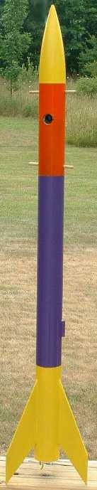
We have named the improved video rocket the EyeSoar. Yes, it does send a solid-state video camera (eye) soaring into the sky. It is also a rocket with an in your face attitude and color scheme. The EyeSoar is designed to allow the use of three different engine sizes, and to reduce rocking and spinning during descent. Our EyeSoar is shown along the left side of this section.
In summary, the EyeSoar is based around the Estes StormCaster. That rocket was modified to accept an E engine (as well as D and Fat C with an adapter). The EyeSoar will indeed fly on all three engine classes (smallest engine: C11-3). The body tube of the StormCaster was modified to create a payload section at the top of the rocket. This payload section held the video camera. A solid balsa tube coupler was used between the payload and the body tube section. A paper coupler was used as a liner within the payload section to snugly hold the camera. The last enhancement was to add an X-style nylon parachute and long shock cord to the payload section. The lower section of the rocket returns via the StormCaster plastic parachute. The rocket (with camera and parachute) weights approximately 9 ounces (without an engine).
Conceptually, the EyeSoar reuses the ideas developed in the first implementation. This includes the use of dowels as pins and rubber bands to hold the sections of the payload compartment around the camera. Holes in the payload section allow access to the camera buttons.
The first alteration that we made to the standard Estes StormCaster was in the engine mount. The following picture shows the parts. Please click on the picture for a larger view.
 |
| Modified StormCaster Engine Mount |
The supplied metal engine hook was replaced with an E engine hook. The E hook is approximately one inch longer. The tube over the engine hook was located 1/4" further in from the bottom of the rocket. This gives the hook a little more play. Note, however, that you cannot move the outer tube back too far, since the fins have tabs which extend to the inner tube. The fins are notched to go around the larger diameter outer tube. The last change made to the engine mount was to cut off the top 2.5 inches of the inner tube. This provides more room for parachutes. The cut piece is lying to the left of the engine mount in the above picture.
The unmodified StormCaster body tube consists of two shorter pieces that are joined with a paper coupler. In the EyeSoar, the shorter tubes are joined, but the top 5.5 inches are cut off to make the payload section (see the comments below on lengthening the rocket). The 5.5 inch section is further cut into 3.5 and 2 inch sections. These are the two sections that enclose the camera, meeting at the middle of the lens line. A combination of hobby knives and Dremel tool bits were used to create the openings for the lens. The following pictures show the payload components and payload section.
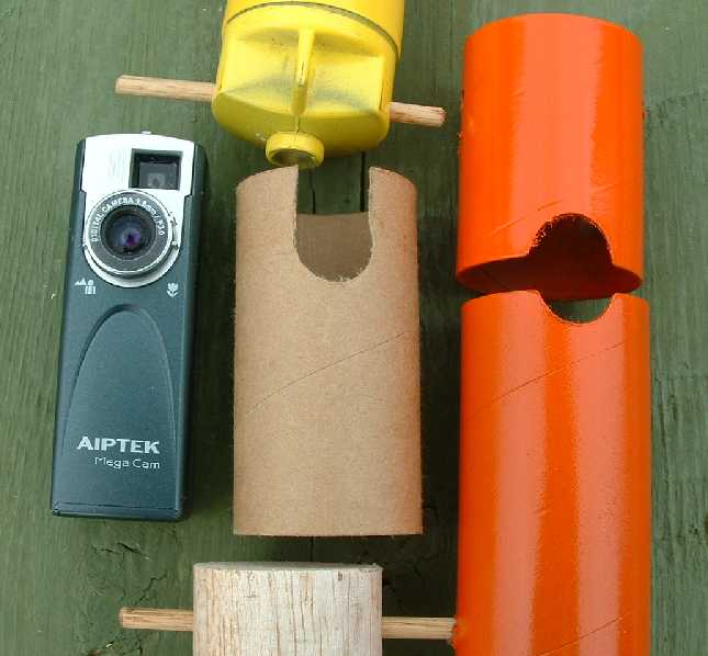 |
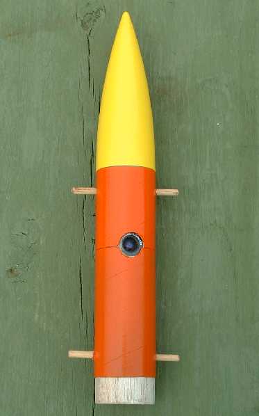 |
| Camera Payload Components | Assembled Payload Section |
The bottom balsa block is 1.75 inches long. The components are sized so that they hold the camera firmly in place. Any slight variations in size can be taken up in the length of the bottom balsa coupler. In other words, you can custom cut the length of the block so that the internal size of the payload compartment matches the external length of the camera. The balsa coupler extends 5/8" to 3/4" inch outside of the payload body tube. This is the portion which seats into the top of the main rocket body tube.
A long paper coupler (the brown tube in the above picture) is used as a liner inside the payload tube. This liner provides additional protection for the camera, and creates a very snug fit for it as well.
3/16" wooden dowels are placed through the nose cone and bottom balsa coupler. These dowels provide mounting points for the parachute harness, and rubber bands that hold the top and bottom sections of the payload compartment together. Two holes on the back side of the top of the payload section provide access to the control buttons of the camera. The dowels are not glued. They can be removed and replaced.
When we launched the first prototype (before the EyeSoar) video rocket, we were very displeased with the large amount of swinging and spinning during the parachute descent portion of the flight. In order to minimize that problem, we made two changes. First, we used a 24" X-form parachute. This style of parachute reduces horizontal drift, which not only keeps the rocket closer to the launch area, but in doing so reduces rocking due to uneven sideways movement. After all, if all parachutes came directly down, on a vertical line, there would be very little swinging of the payload. Second, we also use a long shock cord - perhaps up to 6 feet long. This reduces the disruptive movement of the payload on descent. It is somewhat like making the arm of a pendulum longer, the frequency of oscillation is reduced. The camera points toward the ground on descent, since the payload section is suspended from its side. In that orientation, the payload is much longer than its width, and it tends to align itself with the wind, and experience less spinning than a typical vertical payload section. We can obtain a second descent orientation by disconnecting the harness from the bottom dowel. In this case, the camera will be pointing nearly towards the horizon, with a slight downward tilt. This is also a useful orientation. The following two pictures show the two different harness configurations.
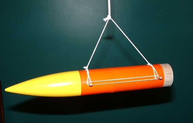 |
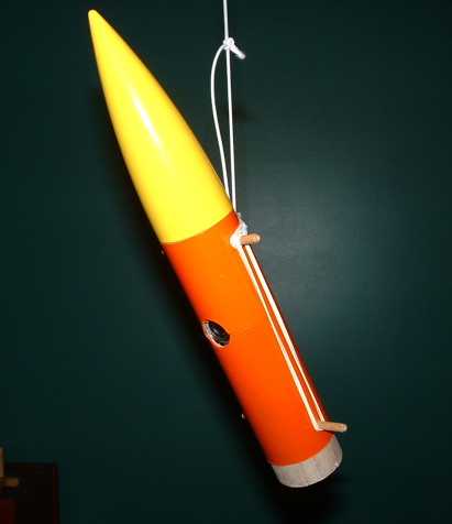 |
| Horizontal Harness Configuration | Vertical Harness Configuration |
In the end, there is still too much movement on descent. Here is the one place where using a much bigger rocket might be helpful.
The parachute attached to a harness made out of small diameter shock cord material (available at most fabric stores). The shock cord is connected to the dowels. The dowel holes were drilled so that they were perpendicular to the direction of the camera lens. As a result, the camera points straight down on descent. A small slit was cut in the balsa coupler so that the shock cord could go from the dowel harness back into the body tube. The parachute is in the body tube on ascent, and needs to be connected to the dowel harness.
The balsa and paper couplers, and X-form nylon parachute, were purchased from Aerospace Speciality Products.
The EyeSoar is launched very much like the first prototype. The rocket is prepped, and then the camera is placed within the payload section, which is secured with rubber bands. The rocket is placed on the launch pad. A letter opener is used to turn the camera on, and place it in video mode, as opposed to still picture mode. The shutter button is then pressed to begin video recording. We usually launch the rocket within a second or two of that point, so that the maximum recording time is available for the flight itself.
Several flight videos can be found on our rocket video page.
The EyeSoar may be a little short. Adding about 4 inches to the main body tube would make it much easier to pack the parachutes, and would improve stability when flying on E engines [in the end I did add 3.5 inches of main body tube]. Perhaps the best way to go is to build the StormCaster with its factory length, then add a separate section to form the payload section. Aerospace Speciality, previously mentioned, carries a full line of body tubes and all of the other parts that we used (except the dowels). Update: As we gained more experience with the rocket, and did the classic spin test, it did become clear that the rocket does need to be longer. This is almost a necessity when using the heavier E-sized engines. I added a few more inches (in addition to the 3.5 inches mentioned before), and kept applying the purple paint. While the nose cone is relatively heavy, which would tend to keep the center of gravity towards the top, the larger engines are also heavy, pulling the center of gravity rearward. The rule of thumb is that the center of gravity be at least two body tube diameters in front of the center of pressure. The spin test should always be done to insure that you have a stable rocket, especially if it has a $100 camera on the top! I suspect that this was not an issue with the initial Scrambler 2 rocket since it could not accept the larger E engines, and because it has much larger fins, which tend to pull the center of pressure rearward.
This digital camera is capable of taking high resolution still pictures. A good future enhancement would be to snap a still at some point in the flight. This would require opening the camera body to get at the electrical contacts that take the picture, and connect those contacts to a timer or other control circuit. The web page: Modifying a PenCam for External Control contains a good description of modifications that appear appropriate for the camera that we used.
In hindsight, the simpler implementation would have been to build the StormCaster to its normal length. I would still substitute the E engine mount, since that engine really provides a high altitude flight for this camera. The payload section would have been made from additional parts. A balsa coupler, body tube, paper coupler, and dowel rod are all that are needed. Be sure to extend the body tube if you intend to use an E engine.
It's no end of fun to fly this rocket, and then connect the camera up to a laptop computer right on the flying field and download the movie. Perhaps all that's missing is audio. If I wanted to add sound, I think that I would simply use one of the small pen-sized recorders used for dictation. I would then use nonlinear editing software on the computer to get the audio in sync with the video.