 |
| AEA CIA-HF with cialog on Notebook |
Greg Ordy
cialog (chia-log) is a no-cost program that communicates with the AEA CIA-HF complex impedance analyzer. The analyzer includes a computer serial data interface (RS-232) which can be used to duplicate many of the control and data collection functions available from the front panel. A serial (COM) port will be required to connect the computer to the CIA-HF.
Beginning with version 1.08 of cialog, the program also works with the N2PK VNA.
While the analyzer can make a number of measurements and data reports, the focus of the device is measuring SWR and impedance over a set of 100 data points. These points are typically characterized by a center frequency and the frequency spacing between data points. The frequency spacing (width) between points ranges from 1 KHz to 100 KHz.
The 100 data points and the range of preset widths makes it possible to cover all of the HF amateur bands with a single scan. This becomes a convenient way to characterize an antenna system across a band. The available data consists of the SWR, resistance (R), reactance (X), and impedance (Z).
The purpose of cialog is to upload data from the CIA-HF, and display it on a graph using a rectangular coordinate system. Data sets can be saved in a file. They can be reloaded to allow comparison with current or other saved data. The data can be loaded by other programs, such as Microsoft Excel, for additional data analysis. The data graphs can also be placed on the system clipboard for transfer to other programs, and printed.
cialog includes an algorithm which resolves the sign of the reactance. The CIA-HF reports all reactance values as positive numbers. The sign information is not available. It is possible to use slope information from the reactance data, or, slope information from the reactance and resistance data, to determine what portions of the reactance data should be assigned a negative value. While the automatic algorithm cannot be 100% accurate in choosing the resolution model, it usually gets it right, and in any case, you can manually select either model, or, disable the feature entirely if you simply want all positive reactance data.
When the CIA-HF makes a measurement, its reference plane is at the connector on the case. Resistance and reactance are measured at that point. In many cases, what we would like to do is measure the characteristics of an antenna which is connected via a coaxial transmission line to the CIA-HF. The effect of the transmission line will be to transform the impedance at the load (the antenna) into a different value at the input to the transmission line, where the CIA-HF is located. cialog accepts the specification of up to four different feed systems, where a feed system is a given length of a particular type of coaxial cable. cialog will use a lossy transmission line model to transform the data at the CIA-HF to the other end of the line, at the load. In addition to transforming the impedance through the cable, the expected loss in the cable will be computed.
In summary, the three important functions of cialog are:
Record SWR, resistance, reactance, and impedance data uploaded
from the CIA-HF. The data is immediately graphed, and can be saved to a file.
Apply a reactance sign resolution algorithm which determines
data which should have a negative (capacitive) reactance.
Transform data reading made at the CIA-HF back through a section of transmission line, computing the data at load, not at the CIA-HF.
|
|
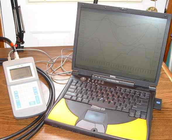
| AEA CIA-HF with cialog on Notebook |
When the CIA-HF is combined with a notebook computer, cialog can be taken to the site of the antenna, which is usually outside.
Here is a screen capture of the cialog program after uploading data from the CIA-HF.
 |
| cialog Screen Capture of Test Cable with 25 Ohm Termination |
In this example the CIA-HF is connected to a 25 Ohm load through a 17.1 foot section of RG-213 cable. If this lash-up sounds familiar, it should. I have used that same test cable and termination on a number of web pages as a load which generates a range of complex impedance values as a function of frequency.
The black trace is the S trace (see the legend), which is the SWR as measured at the CIA-HF. The oscillation in the data might at first be a little disquieting, but if you look at the SWR range on the right, the SWR varies in a very narrow range, approximately 0.1 units. In other words, the minimum SWR on the graph is around 1.85, and the maximum is around 1.95. This is a very narrow range. On most measuring devices, the SWR would be reported as a nearly straight line.
The R and X traces show the resistance and reactance values, measured at the CIA-HF. The reactance resolution algorithm has marked some of the data as being negative. This graph of R and X can be compared against the expected values, developed on another web page. Here is that graph of expected data.
 |
| Lowband and TLA Computed Input Impedance |
The CIA-HF shows a range of reactance data which is reported as 0 Ohms. This issue, the reactance measured near zero Ohms, has been noted on my antenna analyzer comparison page. I do not know if this is a characteristic of all CIA-HF units, or perhaps if my unit is simply out of calibration. In any case, it is what my unit reports.
The last trace shown on the graph, is the Rl trace, which is the resistance at the load. This value was computed by taking the resistance and reactance values measured at the CIA-HF, and transforming them through the transmission line (named Alpha in this example), back to the load. We know that the load is, in fact, a 25.2 Ohm resistor. While the graphed data has some variation, the reported value is approximately 26 to 27 Ohms.
As a second example, I measured the SWR of my 80 meter Inverted Vee. In the first measurement, the CIA-HF is connected to the antenna via approximately 150 feet of 50 Ohm transmission line. I then added about 60 feet of RG-58 line, and made a second SWR measurement. The additional cable should cause the SWR curve to broaden out, due to the loss on the cable. Here is the comparison graph.
 |
| Comparison of SWR Values as a function of Transmission Line Length |
The black trace is the SWR as measured through the longer cable. The red trace is the shorter cable. As expected, additional (lossy) cables causes the SWR curve to become flatter. The effect is subtle, but nonetheless visible through the CIA-HF.
This example demonstrates what is called multiple trace mode, where data from up to five cialog data captures can be compared on a single graph. This comparison is useful for a number of reasons. One might be to evaluate the impact of adjusting an antenna to select the desired point of resonance. One that I like to use is what I call maintenance mode, where I record the characteristics of an antenna when it is first constructed, then check back at some future time to see if the characteristics have changed. The change might be due to a faulty connection, or a transmission line which has become compromised due to corrosion.
The third example is the same Inverted Vee, this time connected to the CIA-HF via 65 feet of RG-58 coax. I specified this length and cable as a feed system to cialog. Here is the graph.
|
|
|
Resistance and Reactance Transformed Through Feed System |
The resistance (Rl) and reactance (Xl) data has been transformed back through the feed system. The data shown is computed by taking the measured R and X data, and transforming them from the input of the feed system to the load (antenna) side. This example also shows how cialog was able to resolve the sign of the reactance, marking it as negative or capacitive below the resonant frequency. The reactance curve crosses zero Ohms near the point of lowest SWR. The reactance becomes inductive (positive) above resonance. The resistance slowly rises as frequency increases. Being an Inverted Vee, the resistance near resonance is closer to 50 Ohms, as opposed to the nominal resistance of 72 Ohms for a dipole at resonance, and reasonably elevated from the ground. This is one of the reasons that the Inverted Vee is popular, it presents a better match to 50 Ohm line.
Finally, using the setup and data from the previous example, the loss through the specified transmission line was calculated and graphed. Here is the dB loss data, plotted with the SWR data.
 |
| SWR versus Transmission Line Loss |
Although, in general, transmission line loss rises with increased frequency, the dominant factor in this case is the additional mismatched line loss, which increases on each side of resonance. The loss on the transmission line is lowest at resonance, approximately 0.6 dB. At the edges of the band, the loss rises to around 1.0 dB.
cialog has been tested on Windows 98, Windows 2000, and Windows XP. Performance (clock speed) of the CPU is not critical. cialog will require a single serial port (COM, RS-232), which is used to connect the CIA-HF to the computer. The Operating Manual provided with the CIA-HF includes a schematic of the required cable.
If you are going to use cialog with the N2PK VNA, and you are running Windows NT, 2000, or XP, it is necessary to use additional software which enables I/O instruction access for cialog. By default, these operating systems do not allow programs direct access to the parallel port hardware. That access is is required since the VNA connects via a printer (parallel) port. Many packages exist which manipulate the access permissions of programs. One that we use is named Userport 1.0. It seems to work well, and is free.
The current cialog self-extracting download file is approximately 700 Kilobytes. The download program is executed to perform the cialog installation. Total installed disk space consumed is approximately 600 Kilobytes (half of a megabyte).
cialog help information is viewed through the HTML Help viewer.
Through this section you can download the current version of cialog.
When you download cialog, you are actually downloading a self-extracting compressed archive file onto your computer. The downloaded file name is a combination of the program name (cialog) and the program major version number. In order to install cialog, you must execute the downloaded file. The install program is in the form of the common installation wizard. You will be asked several questions that will customize the installation for your computer.
One of the installed programs is the cialog uninstall program. You should use this program to remove cialog from your computer. The uninstaller will remove all cialog files, and remove cialog-specific entries from the system registry. The uninstall program will also be available from the Add/Remove Programs applet on the Control Panel.
Although cialog includes an uninstall program, you are responsible for the downloaded self-extracting installation wizard file. In other words, the uninstall program does not remove the downloaded file (it removes the installed files). After cialog is installed, the downloaded file may be manually deleted.
Finally, the software. The following table contains the cialog major releases, in reverse chronological order (most recent is first).
Version |
Release Date |
Description (Size) |
Download File |
Download |
History Information |
1.09 |
October 31, 2004 |
Version 1 (730 KBytes) |
cialog1.exe |
View |
Additional installation and operation information can be found in the on-line documentation (next subsection).
All cialog documentation, both the help information and user's manual, is written in HTML. HTML, the language of the Internet, is also becoming the preferred language for program support documentation. In fact, Windows 98 is shipped with the HTML Help viewer in addition to the older Winhelp viewer.
If you are not running Windows 98, or a more recent compatible operating system, you may not have the HTML Help viewer. The viewer is available from the Microsoft web site, and it will operate on any version of Windows. The viewer will also be automatically installed if you install Internet Explorer 4.0 or higher numbered version. If you do not have the HTML Help viewer, you will not be able to use the help facilities built into the program, or read the user's manual (through the program). Since the documentation is written in HTML, however, we have placed all of the documentation under this web page. This means that you can access all of the information regardless of your help viewer. You can also read the manual before downloading the software.
If you have problems, questions, or comments (concerning this software), please contact me via email, at ordy@seed-solutions.com.
cialog was developed by, and is owned by Seed Solutions, Inc. Copyright ©, 2004, Seed Solutions, Inc. All rights reserved. No warranty of any kind is made as to performance, or fitness of use in any application. Your use of this software is your agreement with these terms. You agree to hold Seed Solutions, Inc. free from responsibility for any damages that may or may not be associated with the installation or operation of the program.
This software may be redistributed in original form. No fee may be charged for redistribution without the prior and specific written consent of Seed Solutions. Inc. This software is licensed for personal and non-commercial use only, and is subject to the export laws and regulations as defined by the State Department of the United States of America, and other applicable regulatory agencies.
Windows, Windows 98 Windows 2000, Windows XP, are either registered trademarks or trademarks of Microsoft Corporation. Other product and company names mentioned on this site may be the trademarks of their respective owners.